
Hugin tutorial — Surveying buildings
This tutorial shows an advanced use of Hugin in combination with a separate 3D modeller, the example used is the creation of a complex 3D survey of a building from a single hand-held photo. It is strongly recommended that you would be familiar both with Hugin and 3D modelling concepts before attempting this technique.
Note: There used to be a great tool for doing this sort of thing called Canoma, but it vanished a long time ago in a series of company acquisitions. It is possible to do something similar in Google Sketchup, but with Hugin we have a sophisticated and accurate lens model that gives us a much higher degree of accuracy than either tool, even if the process is slower overall.
First here is a single photo, note that there has been no attempt to shoot 'straight-on', in fact the converging vertical and horizontal perspective will be useful for fine-tuning the lens parameters:
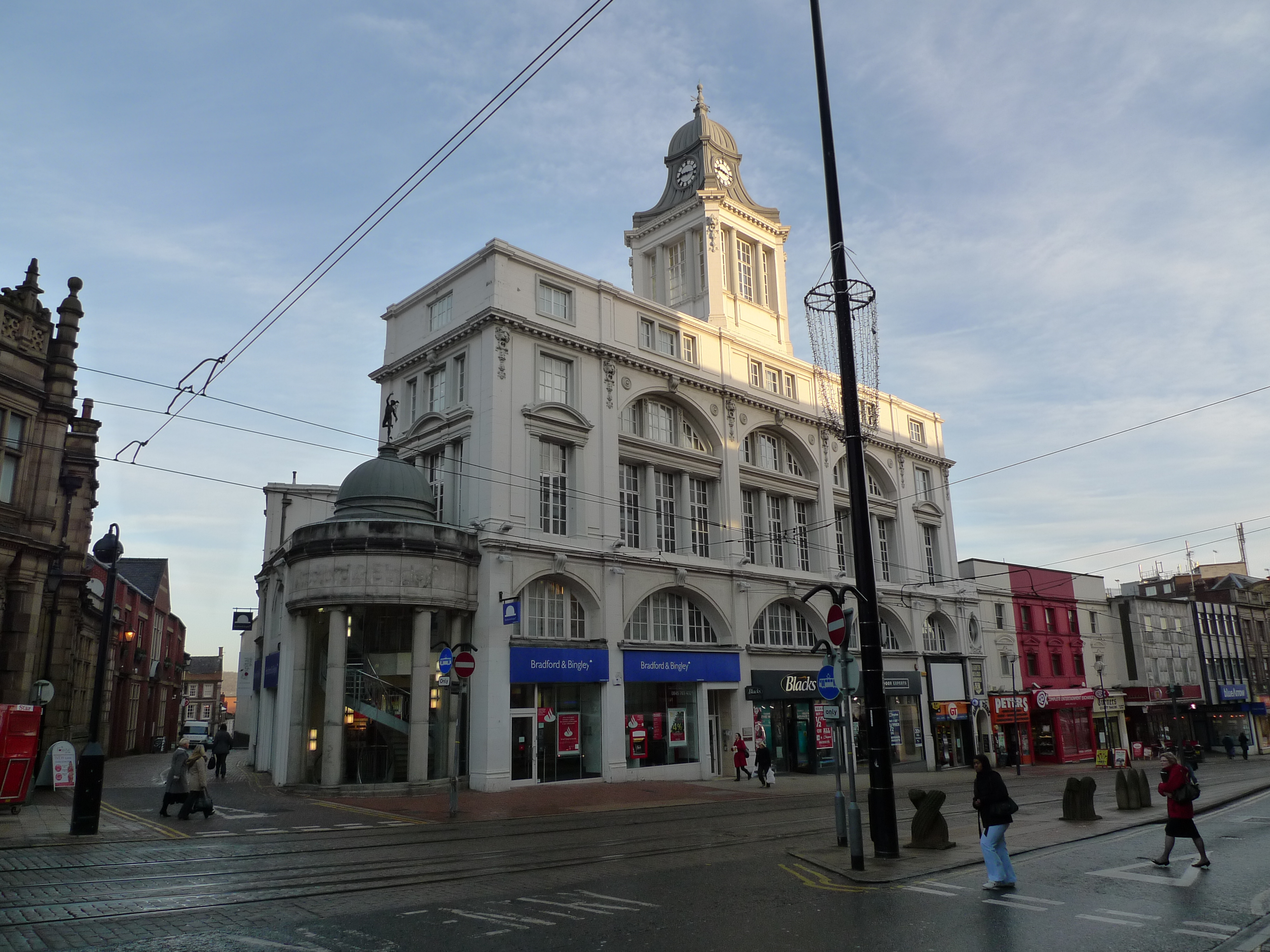
(Click on the image to download the original)
This doesn't have to be a single shot, you can get more detail with a panorama series, however the process in Hugin is exactly the same.
The first thing to do is load the photo in Hugin, set horizontal and vertical control points and optimise to get a straightened elevation of the building. This process is described in detail by the Perspective Correction tutorial, so I won't explain it again here:

Now for this task we need Hugin to get both the lens barrel distortion and horizontal angle of view right. So I have optimised positions, barrel and view - Lots of horizontal and vertical points help correct barrel distortion and the fact that picture has more than one vanishing point means that Hugin can calculate horizontal angle of view with a single shot.
You could also use a pre-calibrated lens setting and skip this extra optimisation step completely. Actually Hugin reads the EXIF FoV as 73.7° and optimisation determined that it is 70.8° - So Hugin is close enough already.
Tracing building elements
The next bit requires a 2D vector drawing tool, I used CAD software, but anything that allows you to trace lines over an image will do, such as Inkscape.
So here I am tracing only building features that are in 'planes' perpendicular to the view direction. Notice that I am treating each of the parallel 'planes' separately and drawing them in a different colour - As they are different distances from the camera they each have a different scale and so can't be connected in a useful way just yet:

So the problem is defining some way to relate these elements together, ideally we would have a section through the building to place them with. Luckily Hugin has a solution, simply rotate the the scene using the Numeric Transform function in the Preview window, enter -90 for yaw and the result is this view at right angles to the previous elevation:

You could create this view in Hugin by creating new horizontal and vertical control points using elements in the side elevation, but as it happens there are not enough features and they are restricted to a limited region of the photo. Rotating the view like this gets better results and is quicker too.
The next step is to trace any elements needed from this elevation, but also draw some rectangles that can be used to position the elements from the previous elevation:

(Notice that relating the clock tower features to the front elevation requires constructing a 'scaffold'. Notice also that to locate the centre of a rectangular element which is not in the 'view-plane' simply draw an 'X' connecting the corners)
This next bit is another piece of Hugin magic. There are some parts of this building that have no normal vertical or horizontal features, notably the clock tower and the cornices. However we do know that these have elements at 45° to both of the main elevations, so go back to the Numeric Transform of the Hugin Preview window and enter a Yaw of -45 . Here is the result:

This isn't just a pretty 'architectural' shift-lens view, the various 45° elements are presented in an exact elevation. We can now trace over the 'hips' of the clock tower roof:

(notice that each side is completely symmetrical even though the foreshortened parts between are not)
The clock tower has some interesting curves, but in reality nearly all curvature in buildings is restricted to a single 'plane' per curve - There is no other way to draw and fabricate these things.
There are more elements that present themselves in this 45° view, notably the mouldings of the cornice and pilasters only have visible edges where they turn a corner, these edges are at 45° to the front elevation. So here are these edges traced:

Again notice that there is a clear symmetry. This outline is actually not the same as the normal 'section' of the moulding, you will need to scale it horizontally by sin(45) (i.e. 70.7%) to get the actual moulding used in the building.
The final Hugin trick is to go back to the original elevation view in the Preview window and enter a Pitch of 90 in the Numeric transform. This view is heavily distorted, but it gives us accurate plan views of all parts of the building where there are horizontal elements:

So again we can trace over these elements, notice that they are also at different distances from the camera so they have different scales and relative positions:

3D assembly
Finally the traced elements can be snapped together in 3D, you can use any CAD or modelling tool for this, e.g. you could do this in Blender.
The important thing to note is that to fit together, each group of elements needs to be scaled as well as moved, but this is a simple one-step process in most 3D modellers:

It is then a matter of extruding elements and turning this from a wire-frame into a solid/surface model:

This bit is nothing to do with Hugin, you need to be reasonably proficient at 3D modelling in your chosen tool.

Locating the camera position
One last thing that it is always very useful to be able to do is to locate the exact spot where the photo was taken.
Go back to the original front elevation rendered by Hugin, the centre of this image also happens to be the 'vanishing point' where converging parallel lines meet. Draw some more 'scaffolding' (shown in red) to relate this point to known features on the building:

..and do the same for the side elevation:

These two scaffolds can then be snapped to the 3D model and used to locate the exact point the photo was taken:

As a check, here is the 3D perspective view looking at the building from this location, overlaid on top of the original photo:

That's it, this technique is more than accurate enough for most architecture, planning and design purposes, though it is no substitute for a detailed survey to discover defects or the actual dimensions of a building.
About
This building is Kemsley House, designed by Gibbs, Flockton & Teather and completed in 1913, it is the home of the Sheffield Star and Telegraph newspapers.
Tutorial by Bruno Postle December 2009